Week 17: Going Wild with Composites
The assignment
Design and produce something with a digital fabrication process (incorporating computer-aided design and manufacturing) not covered in another assignment, documenting the requirements that your assignment meets, and including everything necessary to reproduce it. Possibilities include (but are not limited to) composites, textiles,biotechnology, robotics, and cooking.
I chose composites, because I can use it for my final project. Clicking on the link for composites, I found this description of the assignment:
design and fabricate a 3D mold (~ft2) and produce a fiber composite part in it, with resin infusion and compaction.
I want to make the cell body of a shine through composite that has a texture but is still rigid. A real animal cell membrane has a cytoskeletton that makes up it's form. I will have to do with a rigid membrane. It has to be shine trhough, because inside are LEDs that have to shine trough.
Testing with composites
I don't want my cell to have the rough look that the burlap gives it that is available in the De Waag. So I brought my own testing fabric; white and blue left over cotton. The epoxy I used was Tarbender. You can find the data sheet here. Also I wanted to experiment with embedding beads that can be the ion channels on the cel membrane. First I laser cutted some more 10x10 cm mdf squares that could serve as a mold. The fabric was also cut in the same dimensions. At last I also cut baking paper in 10x10cm. Then I prepared the table for casting. The table was close to the window, so toxic fumes where diluted. I covered the table with waste bags that I sticked together with duct tape. On the table I put:
- a brush
- A jar with aceton to clean the brush
- textile, mdf, baking paper, all 10x10cm
- vaseline as a releasing agent
- A stack of gloves
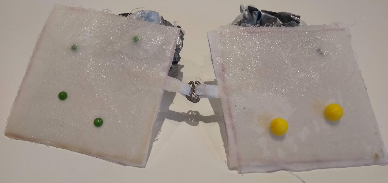
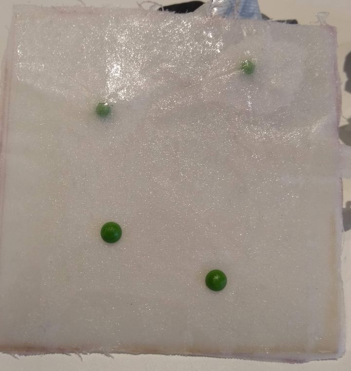
When I had everything ready on the table I put on gloves and took the two jars for the resin to the flow cabinet. I put on a gas mask and started mixing the two components. The ratio had to be 100:41 by weight. First I shook both jars vigouresly for a full minute, as was stated by the description. Then I poured part A in the bigger mixing container. When Emma demonstrated the mixing of the components, we noticed that part A was very viscous. When you have to cast it to another container, it leaves a lot of fluid on the edges. I casted part B in a smaller seperate container and after eaching 41 grams poured it to part B. After that I mixed the two with a mdf left over piece. I put all my waste in the back of the flow cabinet and carried the resn mix to my working table. There I placed a first piece of textile and soaked it in resin using a brush.When it was saoked I put on another piece and repeated. On the top I placed several beads to test if they would hold. I had two kinds of beads that I attached in a few diffeent ways; underneath one layer of textiles, just on top of the textile and more or less embedded in wholes in the textile. Also I tested clips that I might used for the closing of the two halves of the cell body.
After that I placed the test molds with the beads and the clips in a vacuum bag. This was very unsuccesfull. The bag just would't vacuum enough and when I finally was more or less satisfied with the level of vacuum, an hour or so later, the vacuum was gone again. The other test molds I placed under the press.
Designing the cell body
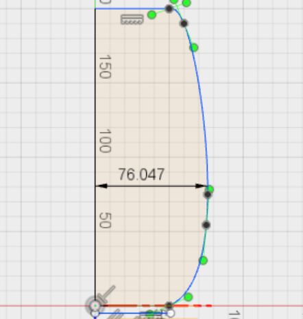
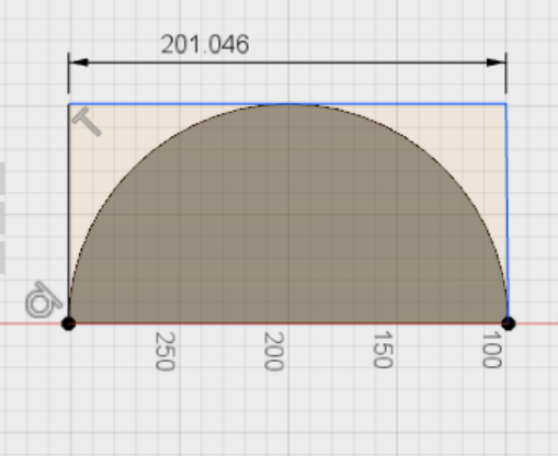
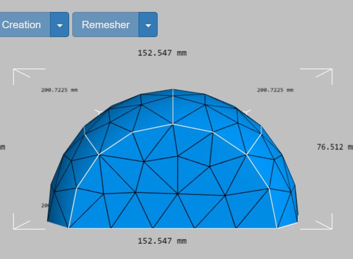
In the first weeks of the course, I have drawn a 3D model of a hair cell. I decided to redraw it. Looking at EM (Elektron Miscroscope) and SEM (Scanning Elektron Microscope) pictures I found that the shape of the cell body is more conical and less blobby then I drew it before.
The method of drawing is more or less the same. I sketch one half of the cell body in Fusion 360, using the line and spline function. Then I revolve the sketch. this time I only revolve it 180 degrees. Because I will make the cell body in two parts. The ShopBot is not able to mill the cell body as a whole. I saved the sketch for another purpose: the skeleton that will cary the LEDS and the boards of the serial network. This I will describe on the page of my final project.
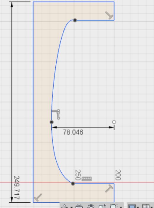
For the cover of the mold I make a new sketch. I copied the outline of my first sketch and pasted it to the second sketch. Then with the offset function I drew a cover for the hair cell body mold. This I revolved again for 180 degrees. This gave me another circulair body. As the foam is straight, I drew a third sketch on the side panel of the second body and extruded it to the other side panel and choose join bodies to make it one body that makes up the cover of the mold. I saved both of the bodies as STL files, right clicking on the bodies and choosing save as STL. A link to the Fusion file is here. The password is FabAcademy2018. The STL files are in this zip file:
STL files hair cell body composite mold
fusion file hair cell body composite mold
Results of the composite tests
Looking at the reults of the composite tests I concluded a few things:
- The beads hold very firm even if just placed on top of the textile. I could use this resin as a glue.
- If I embed beads, I have to use a vacuum bag, but that does not seem to work really well. I leaves bubbles in the fabric. I wonder what the other students experienced with this. I think I will glue any beads to the surface of the cell body after curing.
- The texture of the pressed molds looks much better.

Milling the part 1 of the mold
This is the workflow I used for milling my mold(s):
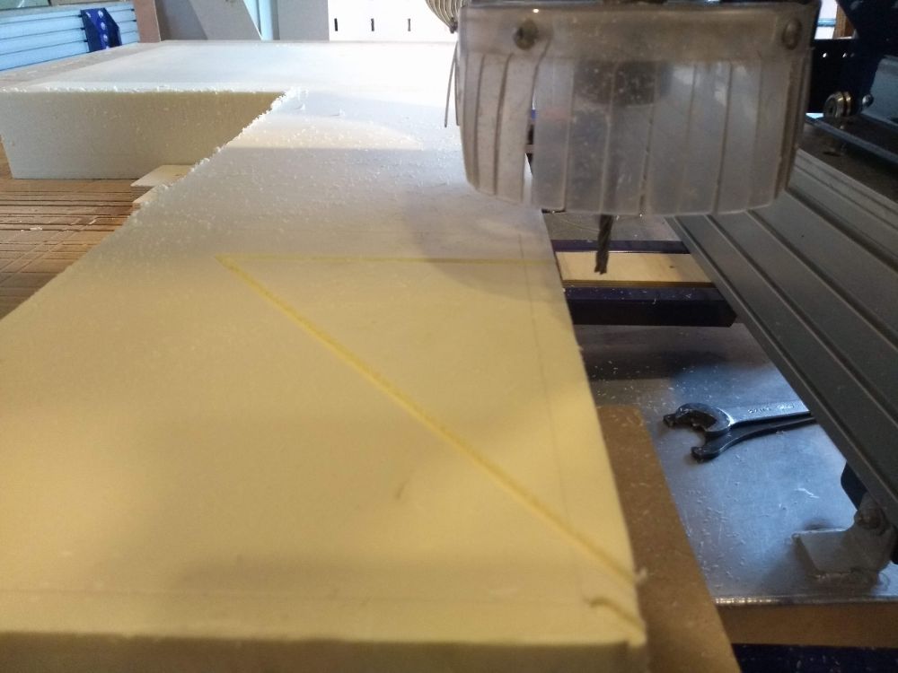
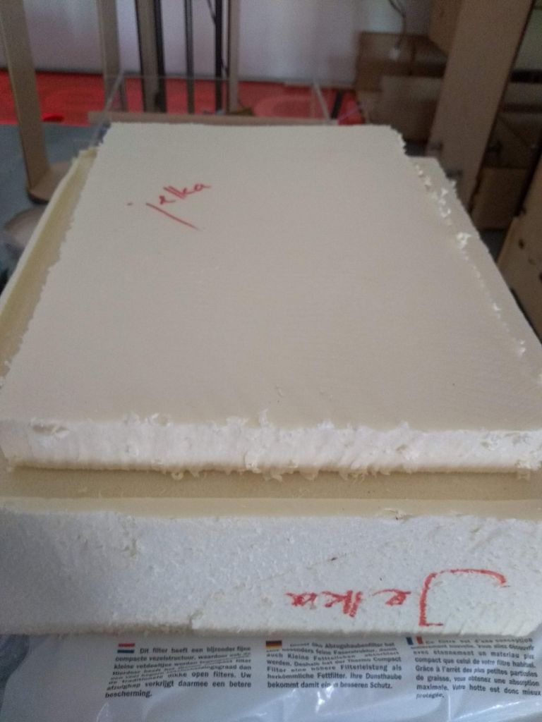
- I placed the foam on the bed and screwed 5 pieces of wood along side it to keep it in place. I forgot to put double sides tape.
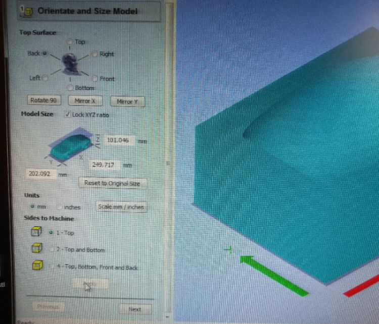
- I opened Part Works 3D and imported the cover of the cell body mold file.
- I choose 'back' for the orientation of the mold
- I rotated the model 90 degrees to exactly fit the piec of foam I placed on the bed
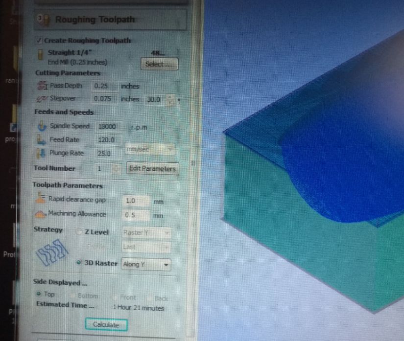
- For the roughening toolpath I chose an 1/4 inch end mill. It was the only choice I had. My model is allmost 8 cm deep, so I have to use a 10cm tool. /the only ones of that size where 1/4 inch. The settings you can see in the pictures below
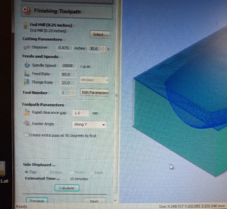
- For the finishing toolpath I had to use the same endmill. I chose to do one extra layer in the Y-direction. This turned out to be useless.
- I didn't use a cutting toolpath. My model is very deep and I didn't want to risk the mill drilling in the bed. Using a saw is much quicker anyway.
- I checked the preview, which looked good and then I saved both toolpaths in one file, as my finishing toolpath has the same tool.
- I turned on the exhaust and then the ShopBot.
- I opened the shopbot software annd pressed K
- Witj the cursors I put the arm of the robot on a convenient place to replace the end mill.
- I unscrewed the protection cap
- I unscrewed the mill holder
- I placed my mill, making sure it was 8 cm out.
- I tightened the mill holder and the protective cap.
- I calibrated X/Y
- I put the mill where I wanted the origin to be, BUT I FORGOT TO SET THAT AS THE ORIGIN
- I calibrated the Z-axis
- I imported my file in Shop Bot
- I turned on the spindle
- I pressed start
Bumpy moments in the milling proces
Right at the start I noticed somethin was wrong. The machine was milling in the air. I stopped the robot and started over. This time setting the origin of X/Y. Luckily I did make a note of the coordinates. Then after 2,5 layers I noticed the model had shifted in the Y-direction for 2mm or so. I stopped the machine again and checked if my foam shifted. I had not. I turned the machine on again and hoped for the best.
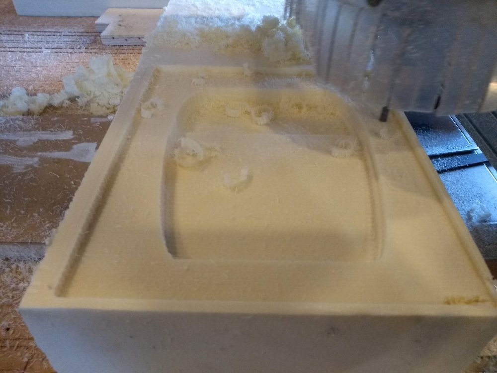
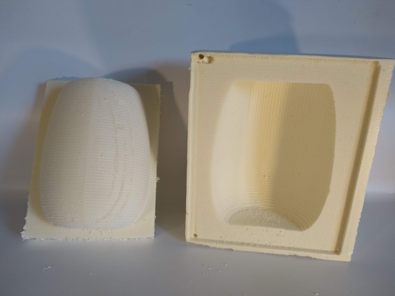
The result was not the best, but sill very good looking.
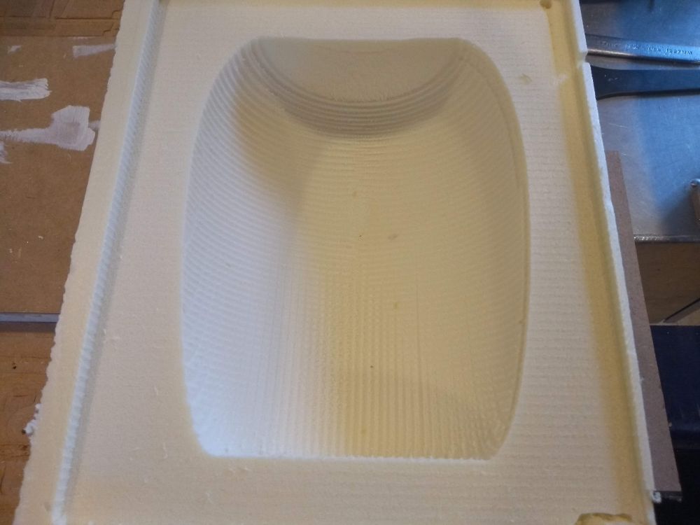
Milling part 2 of the mold
On may 28th I milled part 2 of the mold. I used the same workflow and settings as I did for part 1. Except that this time I did not forget to set the X/Y origin. And that I put double sided tape this time. The strange thing is that again the ShopBot seemed to shift the file in the Y-direction, halfway the process. What is also strange is that the calculation told me the roughening toolpath should take 46 minutes and the finishing toolpath 7. But it was 2 hours and 9 minutes later before the machine was finaly finished. From the pictures below you can see that the result is not really smooth. This is partly because I had to use a very long endmill, for my mold is deep/high. The only end mill in the lab was a 1/4 inch (6,38 mm) end mil that I had to use for the finishing toolpath as well. But mostly it is because I chose a stepover of 30%. that means thet the endmill has an overlap of 70%. I saw in Henk's design, that he used a stepover of 12% and got a much smoother result. I should have done that.
Designing the fabric parts
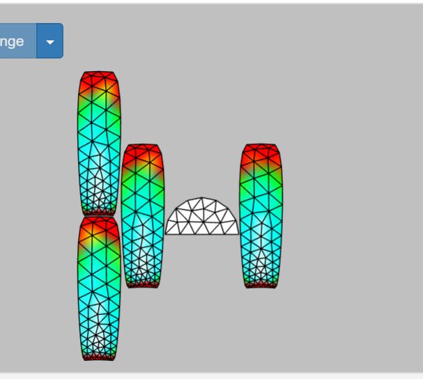
There is a great plug in available for Fusion 360 (and other CAD programs) that is called ExactFlat. I found a great tutorial on YouTube. And I downloaded the plug in here. This is the workflow I followed:
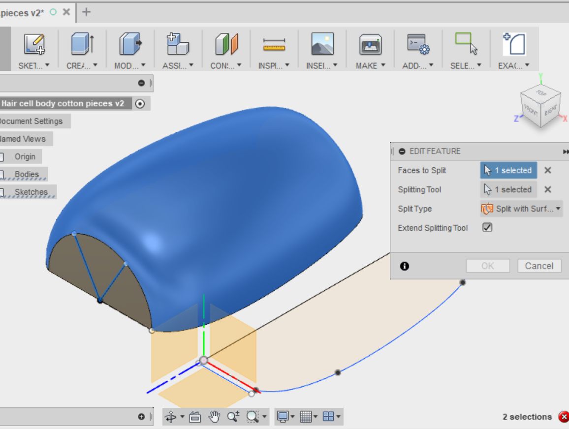
- In Fusion I sketched two lines as a radius on the half circle that forms the bottom of the cell; one with an angle of 120 and one with an angle of 60 degrees. I used the fuction split face to split the cell body in three pieces.
- Choose Modify, split face, splitting tool = line, split type = split with surface. extend splitting tool
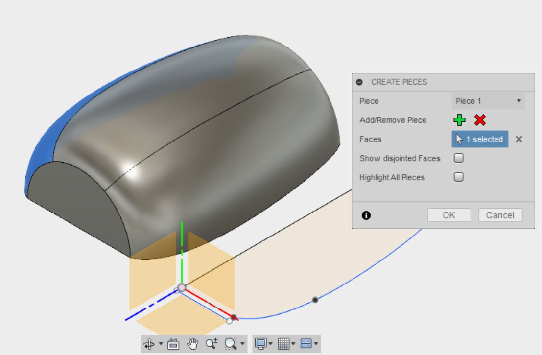
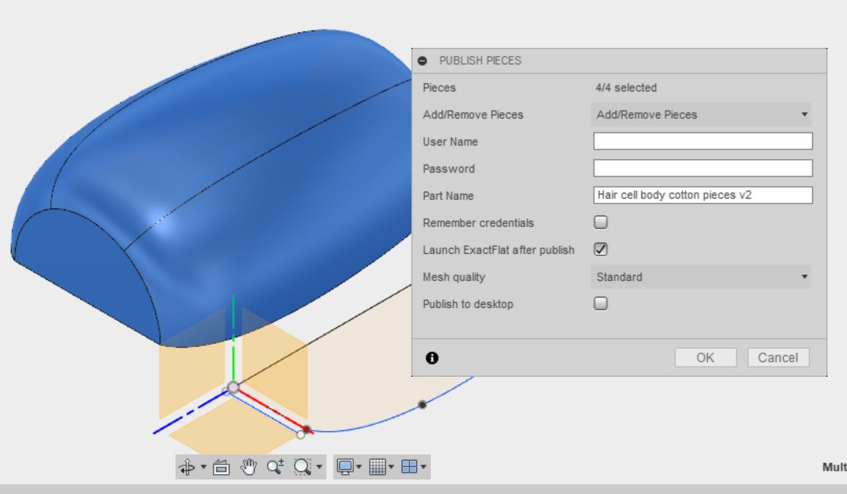
- I Clicked on the ExactFlat icon for Adding Pieces and added all four pieces. Then published it
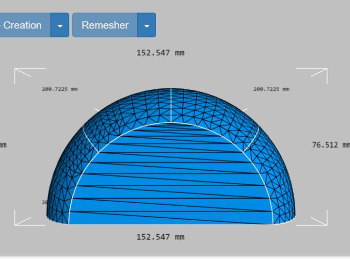
- The ExactFlat program opened in my my browser
- I put the workspace properties on mm and scale 1
- I clicked Remesh, addaptive remesh
- I selected all the pieces by left clicking on them and chose Flatten
- In the pre-flatten menu I choose for Pelt, selected a piece and clicked DONe. This i did for every piece.
- Then I chose optimazation and clicked done. I chose Cloth as material
- Then I chose Arrange and clicked Snap and cose a distance of 10mm
- Clicking on an edge of a piece, makes the adjacent piece lie besides it.
- I chose Finish and set 0 mm for seam allowence, because I will not use a seam
- Then I exported it to PDF, because the strange thing is dat Illustrator will not open the dxf file correctly. If I first exported to PDF, opened in Illustartor and after that saved as CS6, it went fine
- In Illustrator I joined all paths and made the stroke weight 0,1pt
As I said I made two files; one with 4 pieces of fabric, one with 5. You can download my files (AI, DXF and PDF)here:Files hair cell body fabric pieces
Choosing a fabric
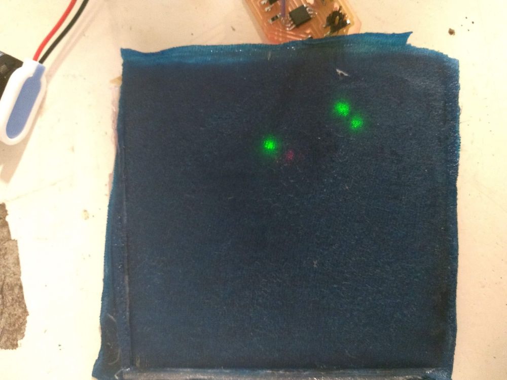
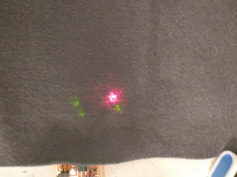
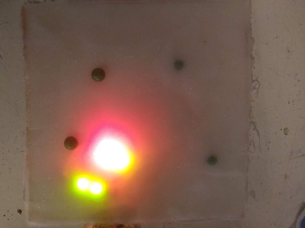
I've tested two coupons with white and blue cotton for a composite. But then I figured I would like felt as a material, just because it is beautifull. But the LED's need to really shine through later on. So i tested that. I put my node board on a 9V battery. This has 4 LEDs in series, so each recieves 2,25V. This is what it will probably be in my final project where I will connect 4 rows of 10-parallel-LEDS strings in series on 9V. Under all three fabrics the LEDs are visible, but under the white cotton the really shine instead of being just pins of light. It will be a light coloured cotton.
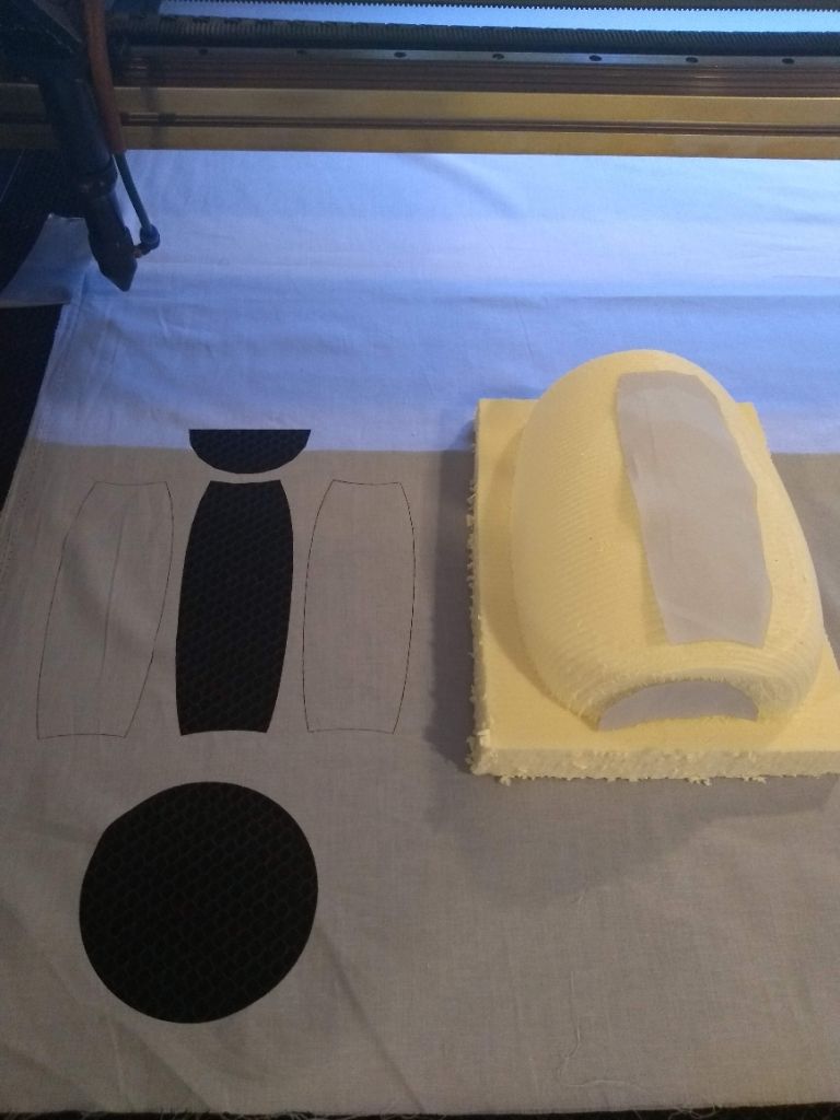
Cutting the pieces
On tuesday may 29 I cutted the pieces of fabric with the laser cutter. I chose a light grey 100% cotton piece of fabric. (I actually took the board with the LEDs to the fabric shop and held it under different pieces of fabric.) I transfered my files to the laser cutter computer. When I imported the file, I allready suspected the pieces where too small. I decided to just go ahead and cut them. I used 40 for speed and 40 for power. the cutting went fine, but indeed the pieces where way too small. I suspect this has something to do with first saving the file to PDF and then making a DXF or AI CS2 file of it. I didn't want to first change my files and then cut again. What I did was measuring the lenght of the cell body mold and measured the edge of the fabric. It came out that the scaling factor was 1,27. So I just multiplied the size of the pieces with 1,27 in the laser cutter software. After cutting I still thought it was a bit tight. The factor 1,35 worked out great. This was for the 4-pieces design. for the 5-pieces design I had to use a factor of 1,40. I want to use 3 layers of fabric, so for each design a cut 4 sets. This way I had one emergency-set for every design.
Laying up the cotton layers on the mold
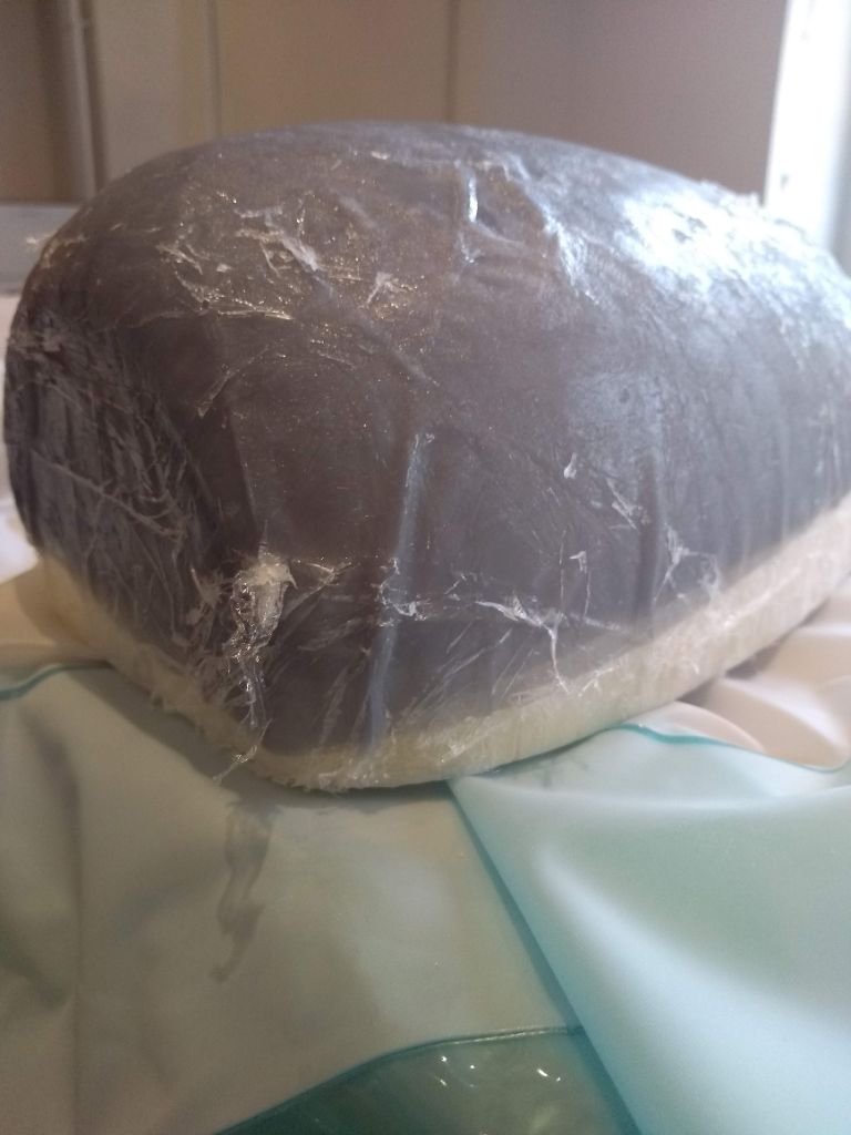
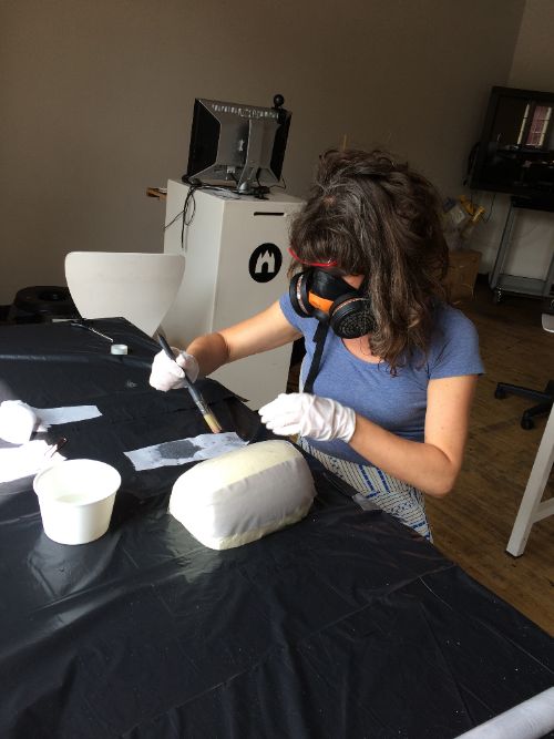
On wednesday morning I layed up my mold with the cotton and Tarbender epoxy. You can find the data sheet here. First I sanded my mold with P80 sanding paper, finishing with P180. The last one didn't really add smoothness though. Then I prepared the table like I did for the testing coupon. I put plastic foil on both of the mold parts, fixing it with sticky tape. The plastic foil I covered with vaseline. And then piece for piece I layed up the mold. Just like I did when I was making the testing coupons. I mixed part A and B like I described with the testing coupons. I put the brush in the liquid epoxy and put it on the fabric. When the fabric was really soked, I placed it on the mold and pressed out the bubbles with my fingers (in gloves!). I started with 3 pieces. On top of that I layed the four pieces and ended with 3 pieces again. This way I had no edges that could be left open during the curing.
While I was putting the mold in the covermold, I realized the presure would not be evenly spread over the surface. Most of the pressure would be in the bottom and less on the sides. Because the of the shopbot making mistakes the two old parts don't fit perfectly anymore. If I had a very thick layer of fabric and epoxy it wouldn't have been a problem, but my fabric is very thin because I want it translucent. I decided to cover the mold in plastic and put it in the vacuum bag.
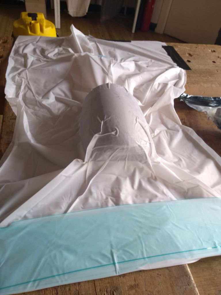
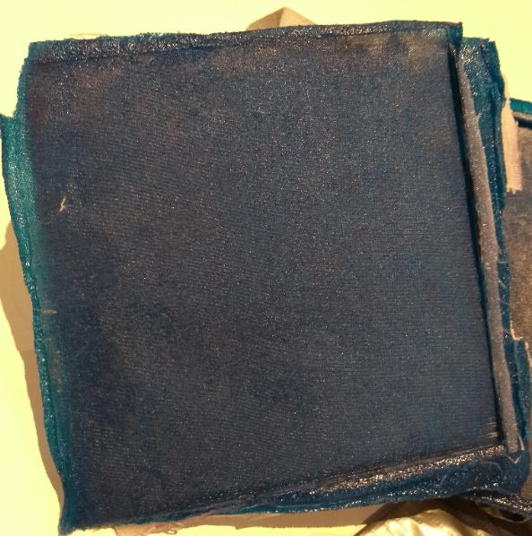
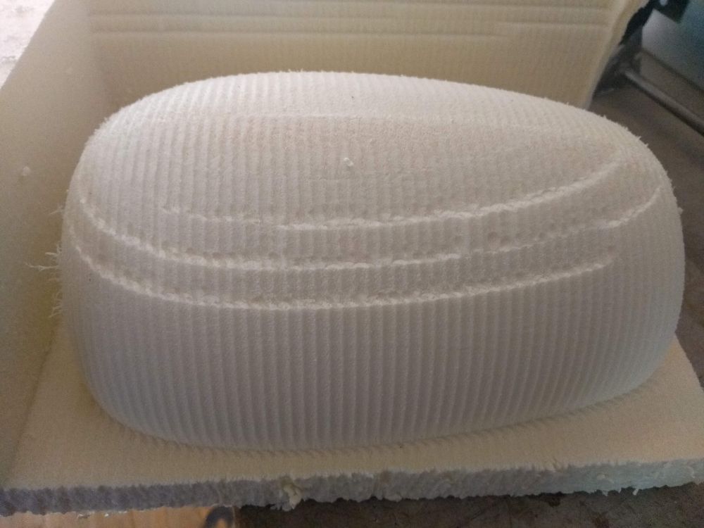
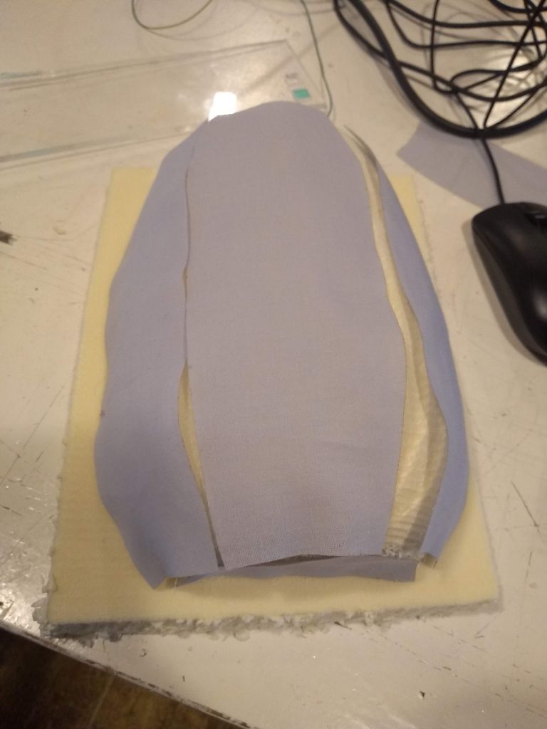
The result
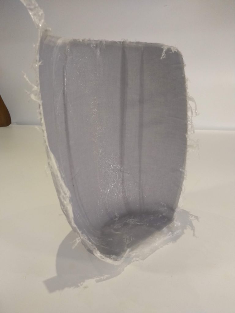
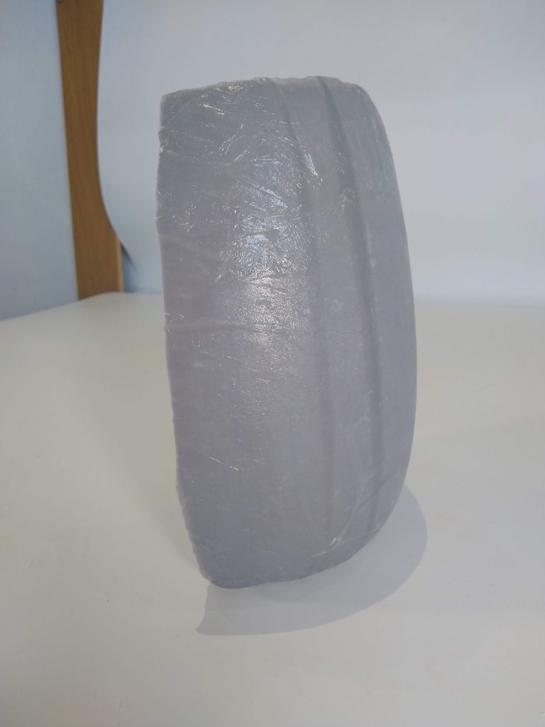
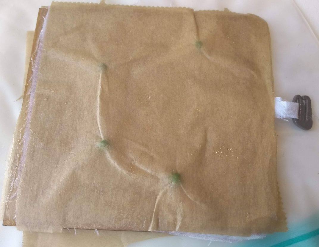
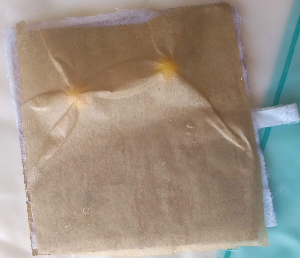
Om thursday morning I unpacked my mold from the vacuum bag. I unwrapped the platic, cleaned the vaseline of with soap, 4 times and cut off all the ugly edges with a Stanley knife.
I am not extremely happy with the result. There are a lot of folds and ugly patches of epoxy spilling from the fabric. Most of it is because of the platic foil I used. It just wrinkles into the epoxy and leaves a print.
Intentions for the second half of the cell body
For this weeks assignment I am done. For my final project I will make another half of the cell body. I will try baking paper instead of plastic foil and cut that in the same shape as I did with the fabric on the laser cutter. I will also put the mold in the cover-mold and press is with glue clamps.